Non-invasive TMF crack growth measurements with IRT
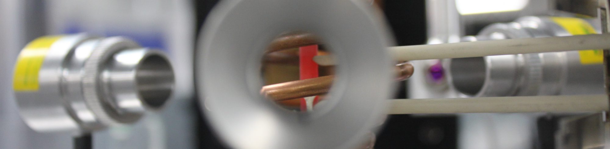
Precise and stable non-invasive temperature measurements were developed using infrared thermography (IRT). This approach was also used to measure and understand crack tip heating in induction coil as well as innovative measurements of TMF CG rates, Figure 1. The method enables measurement of crack length and removes complications with PD probes and coil interferences.
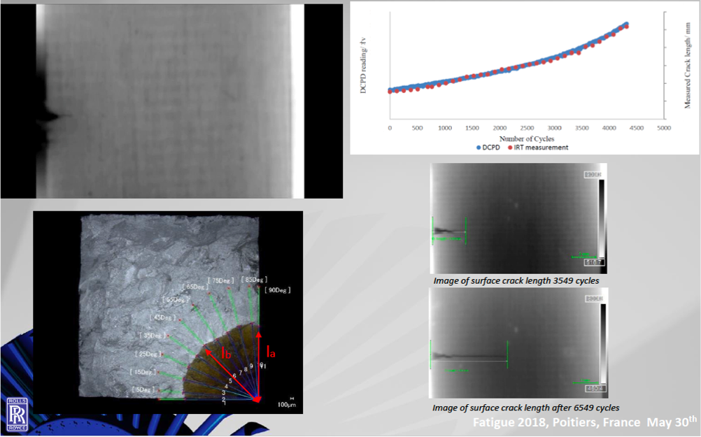 Figure 1: Non-invasive TMF crack growth measurements with IRT. Courtesy of Dr Jon Jones, Swansea University, UK.
Static and dynamic crack tip heating
Induction coils have historically been the preferred method of heating samples in TMF due to the potential for rapid heating rates and easy access for forced air cooling. This enables rapid TMF cycles which can minimise overall test time. It also provides the opportunity for non-invasive crack length measurement, through optical methods. However, other methods have been developed, including resistance heating and the use of lamp furnaces. In notched specimens with non-linear geometries for crack initiation testing, lamp furnaces have been preferred due to the perceived risk of non-uniform heating.
Crack monitoring techniques also require consideration when choosing a heating method, since access to the material and potential conflicts with the technique may occur. Direct Current Potential Drop (DCPD) approaches have historically been used at Swansea University (SU) due to the improved resolution over optical methods, but investigation is required as to whether consistent readings can be obtained within an induction field. Developmental work at SU previously sought to investigate the use of induction heating by initially comparing isothermal testing conducted under induction heating with a more traditional split radiant furnace. Exploratory testing was conducted on the polycrystalline nickel superalloy, Waspaloy, using available square section 10x10mm and 7x7mm uniaxial test specimens. The crack was initiated from a starter notch machined into the corner of the specimen, with a depth of 0.35mm. It was clear that at 650°C and an R ratio of 0.1 in Waspaloy, the effects of testing via induction heating were negligible, when compared to results from a radiant furnace. Furthermore, no effect was seen in the growth rates when a reduced volume (7x7mm) specimen was employed under induction heating. Further investigation of the effect were undertaken in DevTMF utilising a quartz lamp furnace. Diverse coil designs have been also investigated to discover the best design to provide thermal gradients both axial and radially as well as the required heating rates to meet with the current TMF standards and specimen designs in DevTMF.
Through investigations of coil design and other validation tests, it appears that excessive heating of the crack tip is minimised in nickel alloys, due to the relatively high thermal conductivity associated with nickel. However, more significant effects have been seen in Ti6246, which is perhaps unsurprising since the thermal conductivity of titanium is <25% that of nickel. Although only qualitative findings have so far been recorded, crack tip heating appears to be more significant in Ti6246, and this will be further investigated as part of the path to standardisation through thermography investigations. For more details, please see https://doi.org/10.1016/j.ijfatigue.2018.12.015.
Viscoelastic-viscoplastic modelling of material behaviour
Material deformation behaviour is time dependent in many situations, especially at high temperatures. Stress states measured in metals held at constant strain will reduce with time through the accumulation of inelastic strain while loading rates will influence the apparent Young’s modulus with stresses relaxing well below the yield stress for the material. Despite these observations, it is common to see attempts to model the constitutive response of metals at high temperature using unified elastic – viscoplastic assumptions. The literature is rich with examples of various viscoplastic models applied to nickel-based superalloys of which many are based on the work of Chaboche and Rousselier, e.g. here and here. Applications of combined viscoelastic and viscoplastic model formulations are not so common in the literature. A viscoelastic-viscoplastic constitutive material model capturing cyclic plasticity and viscous flow was developed in DevTMF, Figure 2. More details can be found here. A subroutine for the material model was written for integration in commercial FEA codes. Crack initiation life was estimated using a damage accumulation model based on the memory surface concept of Jiang. To account for elastic damage, a simple critical plane search algorithm, calculating stress tensors experienced by a particular plane in the material affecting fatigue life, was considered. To reduce CPU time and increase efficiency while saving energy, additional subroutines for cycle jumping procedures were developed.
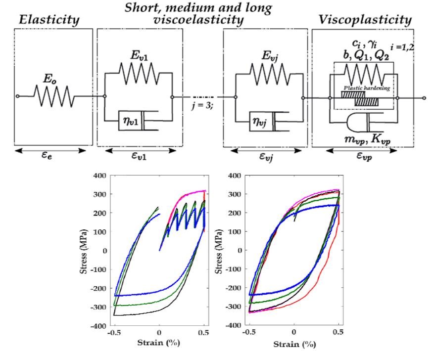 Figure 2: A schematic (rheological) representation of the viscoelastic-viscoplastic model and example cyclic data (P91 Chromium steel). Courtesy of Dr James Rouse, the University of Nottingham, UK.
TMF CG modelling
For simulation and prediction of TMF CG, a model accounting for fatigue, creep crack growth and a participation size effects was developed, Figure 3. The model has used the work of Bouvard et al. where the long crack growth was decomposed linearly into two components to calculate for fatigue and creep mechanisms. As the changes in stress intensity factor are dependent on temperature under thermo-mechanical fatigue conditions, a reduced stress S(t) has been introduced with the temperature dependence modeled using an Arrhenius type function. Under the TMF test conditions used in the project, it was found that the TMF IP was strongly dependent on the microstructure. Therefore, a precipitation size dependent parameter S was developed to account for influence of precipitation size. More details can be found in the paper published here.
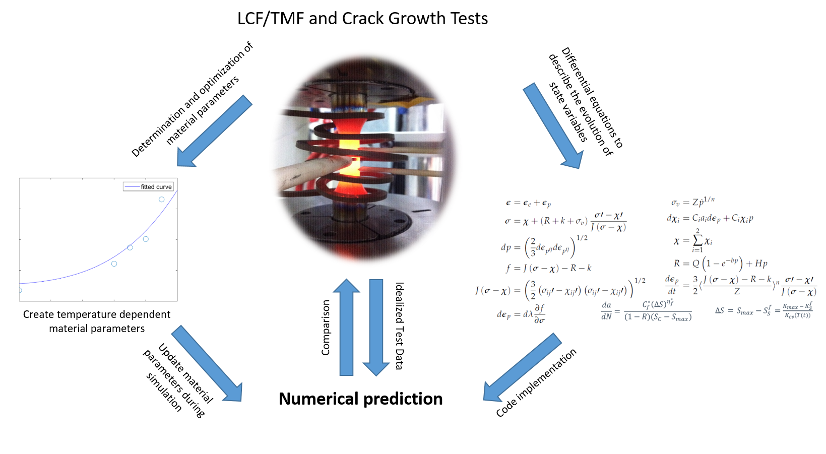 Figure 3: A schematic representation of the TMF crack growth model. Courtesy of Dr Benedikt Engel, the University of Nottingham, UK.
Modelling of Young’s modulus decrease on SIF
To improve the TMF CG model, further investigations have been performed on effect of changes in Young’s modulus around crack tip. Generalised crack tip modelling scripts to correlate plastic strain with degradation in Young’s modulus (as a function of accumulated plastic strain) and SIF were formulated, Figure 4. It is found that even a small decrease in Young’s modulus gives a difference on the SIF at the crack tip, which impacts the crack growth and shape. A new project focusing on this is on-going at the University of Nottingham.
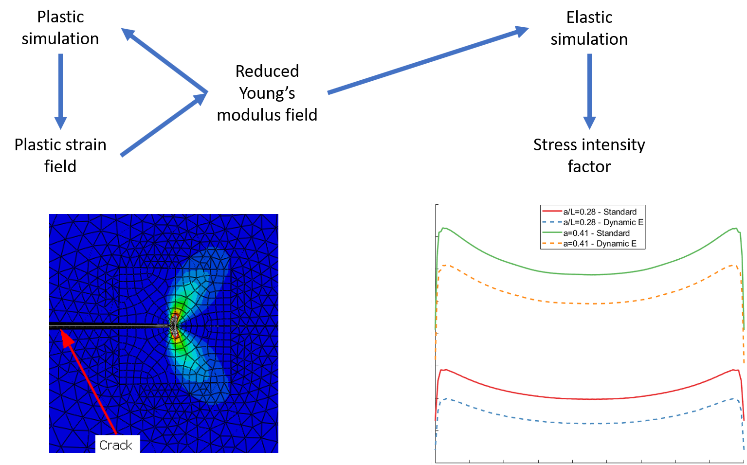 Figure 4: A schematic representation of SIF simulation based on plasticity-induced changes to Young’s modulus. Courtesy of William Lavie, PhD student, the University of Nottingham, UK.
The models and methods were validated and evaluated for various loading conditions showing good agreement with the experimental data in most cases.